WAEC 2026 Candidate Class

CHIATECH ELECTRICAL WIRING TUTORIAL FOR WAEC 2026-2027

A practical, exam-ready tutorial for candidates using Electrical Wiring and Maintenance Work past questions as the foundation for Solar PV installation skills, safety, testing, wiring diagrams, machines, batteries, illumination and entrepreneurship.

A-One expert tutor
Guided practical teaching
A-One candidate class
Focused candidate class
A-One study reminder
Consistent study rhythm
A-One Tutorial Center brand mark
A-One Tutorial Center

Syllabus Exploration

Study these topic families before attempting the tests. Each family appears in WAEC-style practical technology questions and connects directly to Solar PV installation work.

Safety Wiring Machines Testing Solar PV

Workshop Safety & First Aid

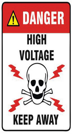
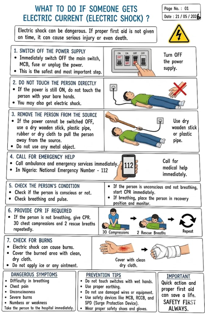
Recognize live conductors, damaged insulation, wet floors, poor earthing, wrong tools and overloads. Rescue shock victims by isolating supply first, then using dry insulating material if isolation is delayed.

Conductors, Insulators & Joints

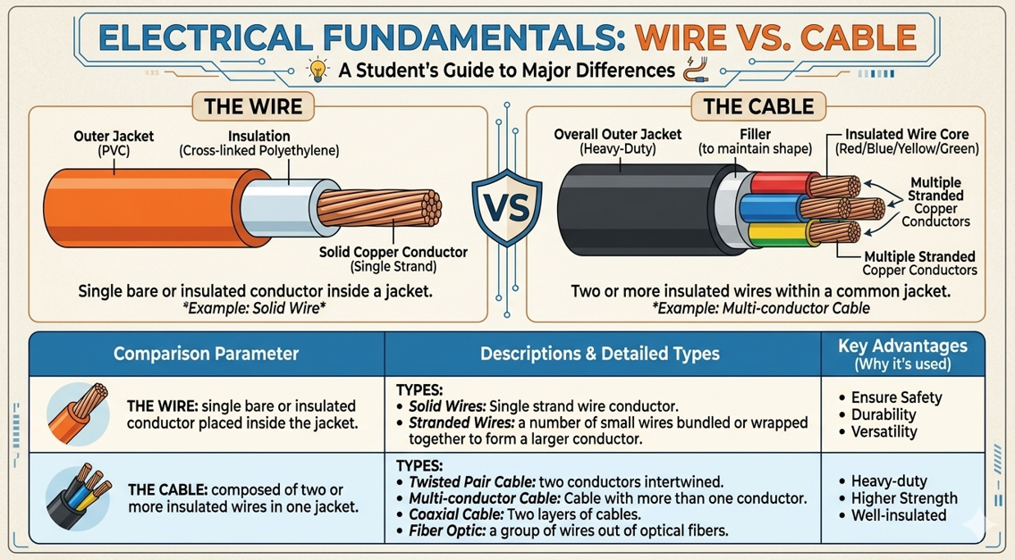
Know copper, aluminium and brass as conductors; PVC, rubber, porcelain, mica and glass as insulators. Practise tee, married, Britannia and straight-through joints.

Cables, Conduit & Wiring Systems

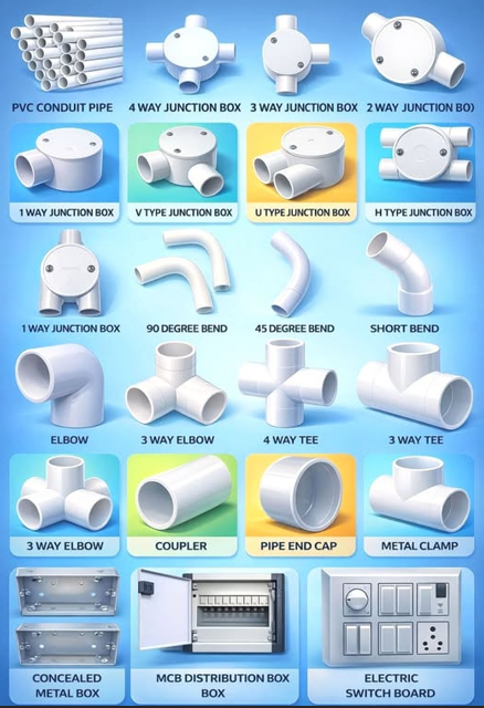
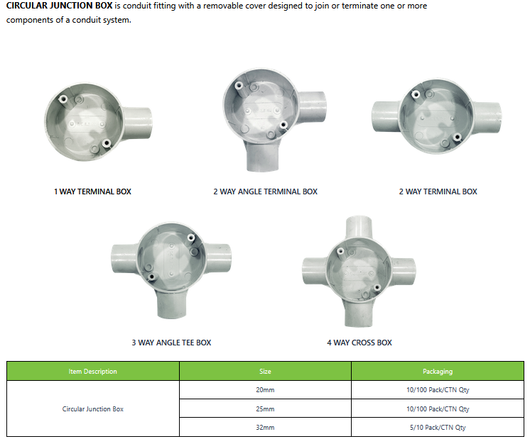
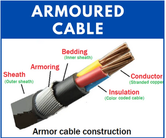
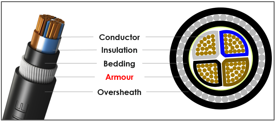
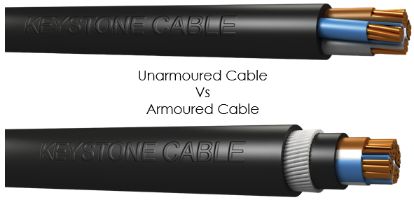
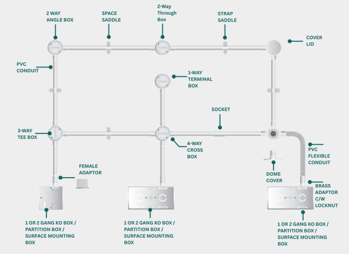
Revise PVC cable, armoured cable, MICC, conduit boxes, saddles, trunking, cleated wiring and surface wiring. Always remove conduit burrs before drawing cables.

Domestic Installation

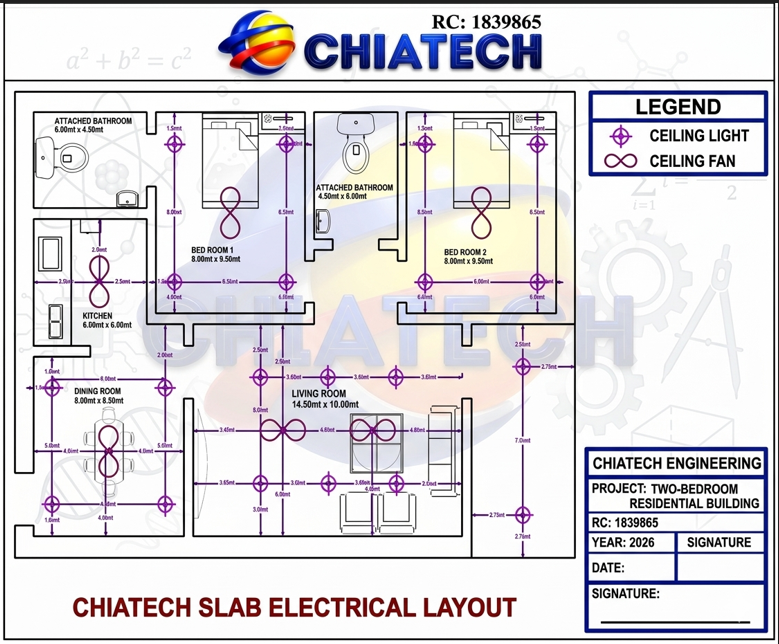
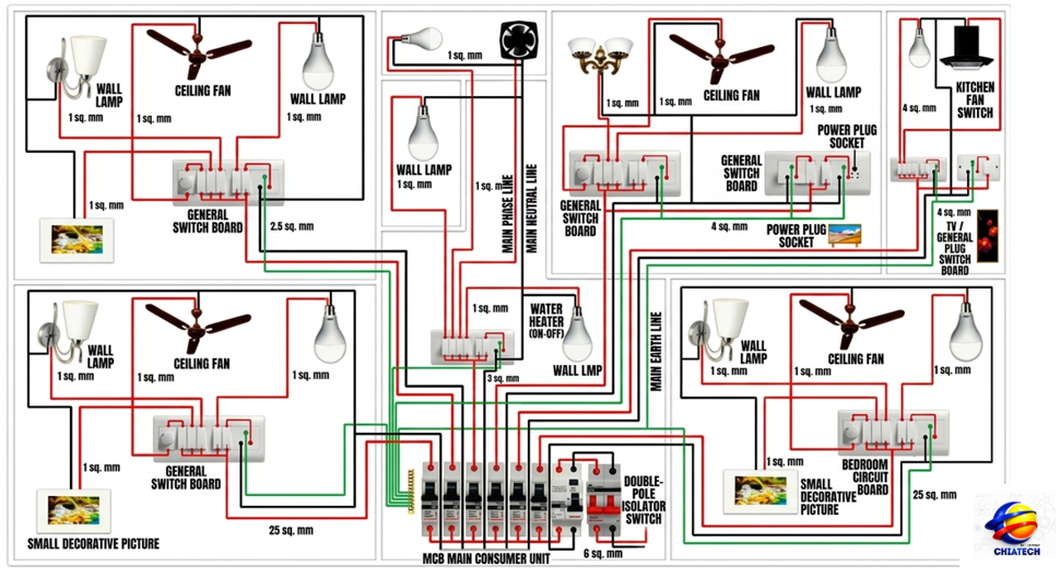
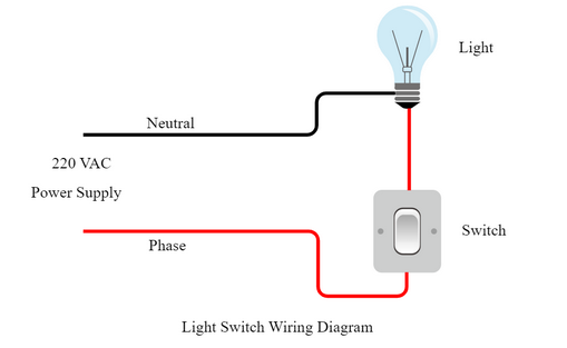
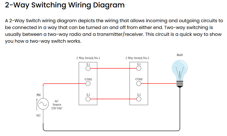
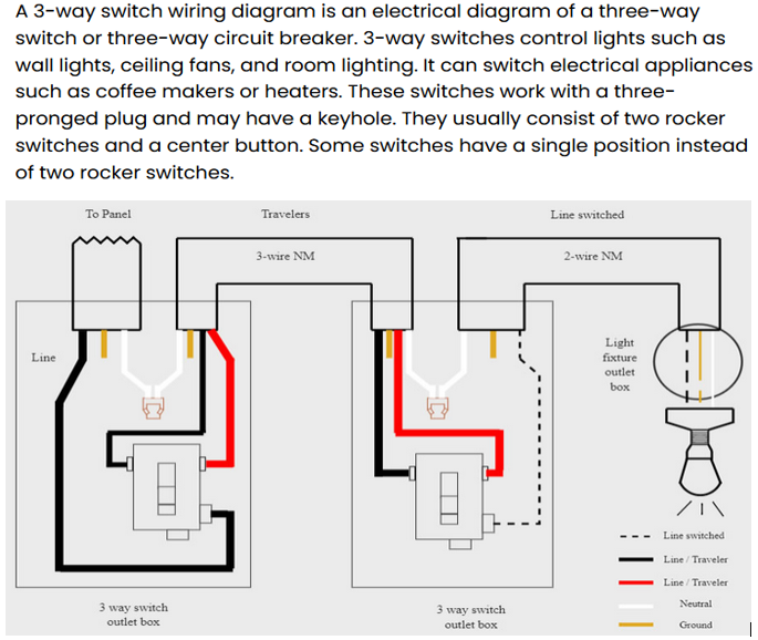
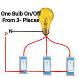
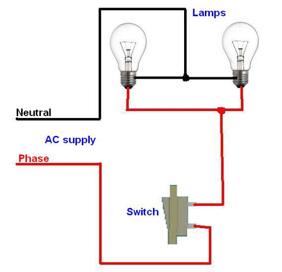
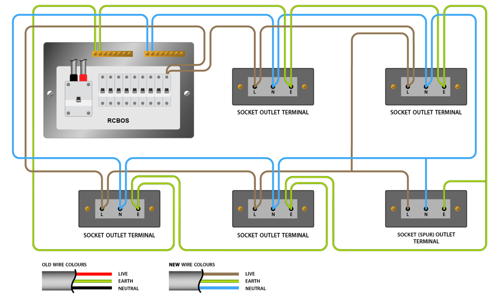
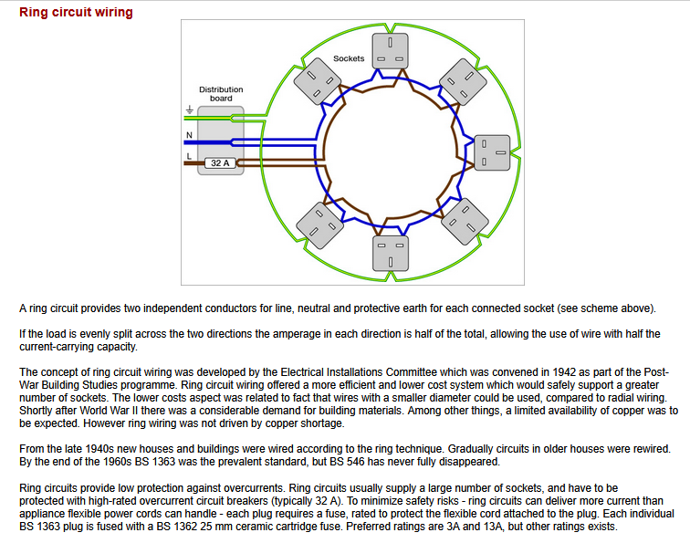
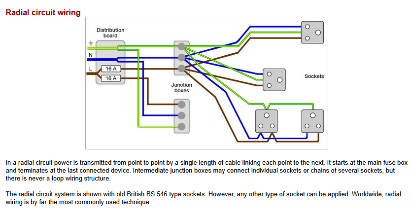
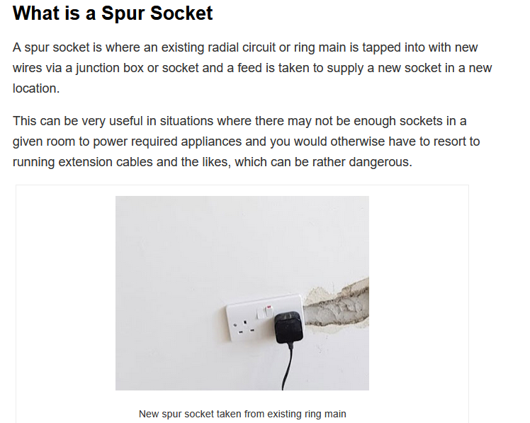
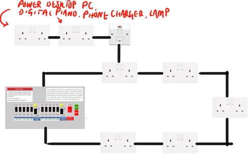
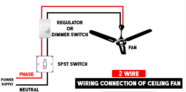
Master one-way switching, two-way switching, lamps in parallel, ring circuits, spurs, consumer units, final sub-circuits and correct socket/switch mounting positions.

Protection, Earthing & Testing

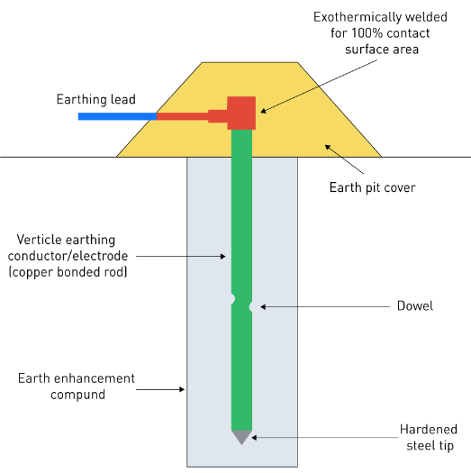
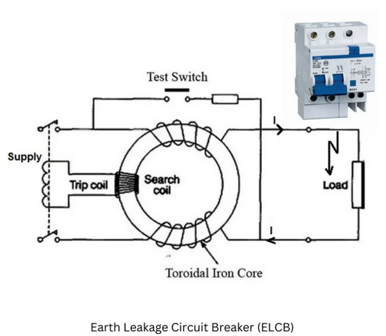
Protective devices prevent shock, earth leakage, excess current, fire and equipment damage. Common tests include polarity, continuity, insulation resistance and earthing tests.

Cells, Batteries & Illumination

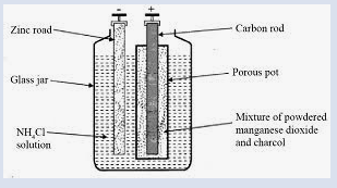
Understand primary and secondary cells, Leclanche cell defects, battery charging precautions, maintenance factor, sodium lamps and illumination calculations using E = I / d2.

Machines & Motor Control

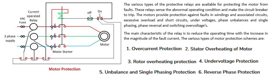
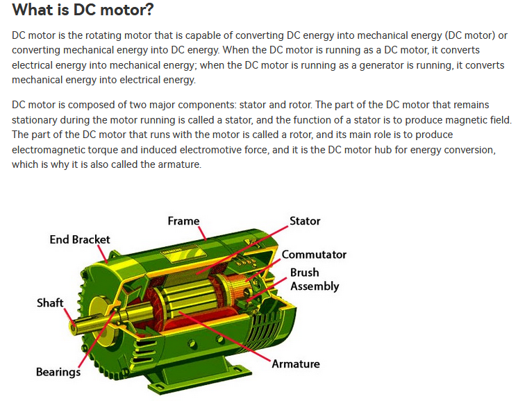
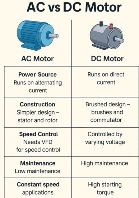
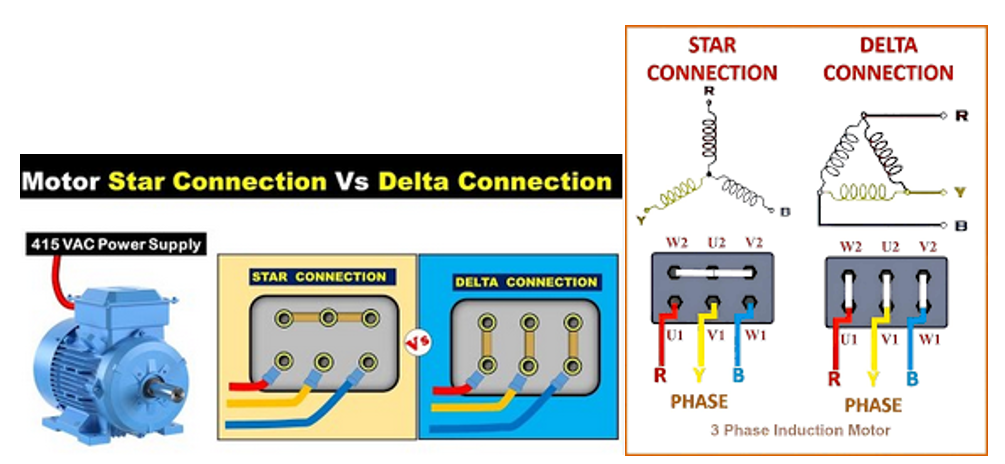
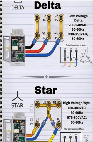
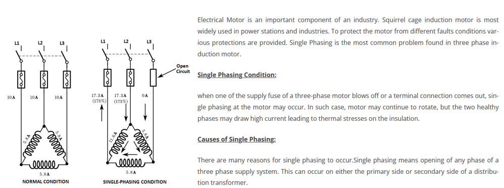
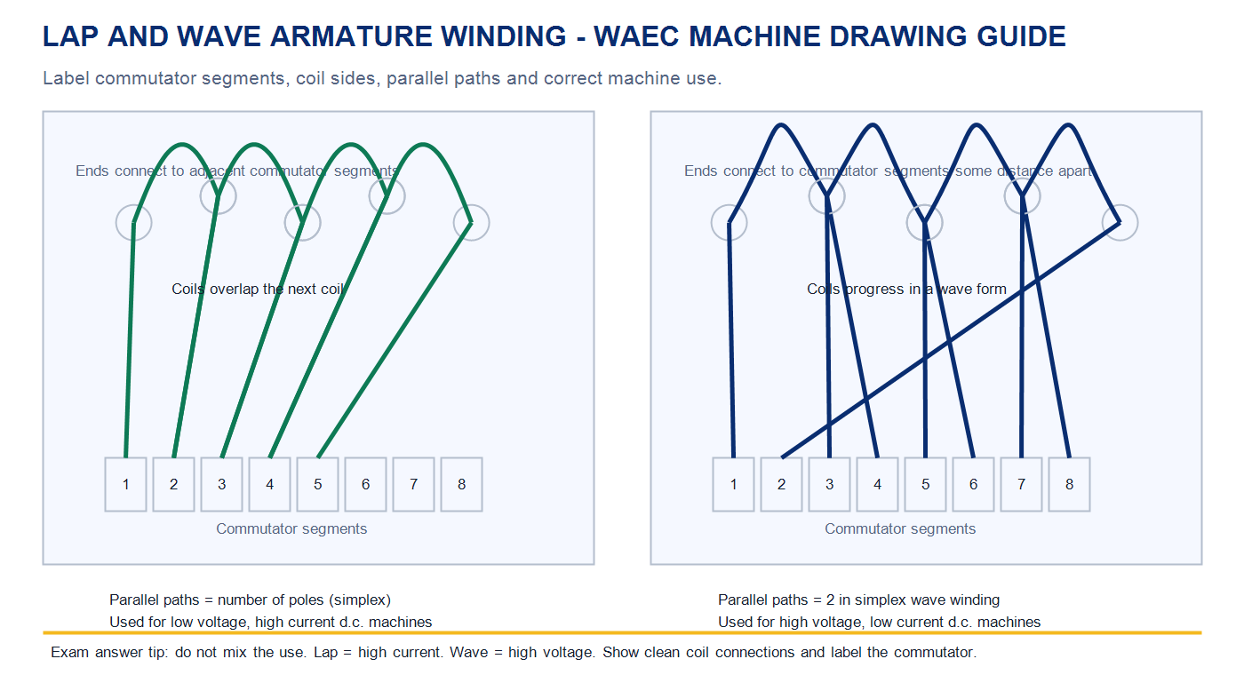
Revise d.c. machine parts, back e.m.f., a.c. motors, induction motor starters, star/delta connection, single phasing, motor enclosure and rewinding procedure.

Business & Entrepreneurship

Know proposal components, start-up funding, business records, budgeting, small workshop registration requirements and factors for starting an installation business.

Formula Cards by Topic

Write the formula, substitute values, add the correct unit, then box the final answer. WAEC calculation questions reward method and unit discipline.

Basic Electrical Laws

Ohm's law
V = IR; I = V/R; R = V/I
Resistance
R = ρℓ/A
Units
V in volts (V), I in amperes (A), R in ohms (Ω), ℓ in metres (m), A in square metres (m²) or square millimetres (mm²) as stated.

Power and Energy

Power
P = VI; P = I²R; P = V²/R
Energy
E = Pt
Conversions
1000 W = 1 kW; 1000 Wh = 1 kWh; 1 hp = 746 W.

A.C. Circuits

Single phase
P = VI cos φ; S = VI
Three phase
P = √3 VLIL cos φ; S = √3 VLIL
Units
Real power in watts (W) or kilowatts (kW); apparent power in volt-amperes (VA) or kilovolt-amperes (kVA).

Illumination

Illumination
E = Φ/A
Point source
E = I/d² for normal incidence
Units
E in lux (lx), luminous flux Φ in lumens (lm), luminous intensity I in candela (cd), distance d in metres (m).

Cables and Voltage Drop

Voltage drop
Vd = (mV/A/m × I × ℓ) ÷ 1000
Cable current
Higher ambient temperature lowers safe current rating.
Conversions
1000 mm = 1 m; 1000 mA = 1 A; 1,000,000 Ω = 1 MΩ.

Cells, Batteries and PV

Battery energy
Wh = V × Ah
PV array
Parray = Pmodule × N
Charging estimate
t ≈ Ah/Ichg, then allow for losses.

Machines and Motors

Synchronous speed
Ns = 120f/P
Slip
s = ((Ns − Nr)/Ns) × 100%
Efficiency
η = (Pout/Pin) × 100%

Generator and Transformer Ideas

Induced e.m.f.
e ∝ ΔΦ/Δt
Transformer ratio
Vs/Vp = Ns/Np
Exam meaning
A faster change of magnetic flux produces greater induced e.m.f.; transformer voltage ratio follows turns ratio.

Armature Winding Facts

Simplex lap
A = P
Simplex wave
A = 2
Use
A is number of parallel paths and P is number of poles. Lap suits low voltage/high current; wave suits high voltage/low current.

Installation and Business

Ring-circuit spur rule
Number of spurs = socket outlets ÷ 3 for the past-question style used here.
Costing
Total cost = quantity × unit price; amount borrowed = total cost − capital.
Percentage
% = (part/whole) × 100.
Important conversions: 1 kV = 1000 V 1 kA = 1000 A 1 kW = 1000 W 1 kWh = 1000 Wh 1 kΩ = 1000 Ω 1 MΩ = 1,000,000 Ω 1 m² = 1,000,000 mm² 1 hp = 746 W
Solar PV bridge: Solar PV work uses the same core skills: correct cable sizing, protective devices, earthing, battery safety, polarity, insulation resistance, conduit practice, load planning and preventive maintenance.

Candidate Fact Sheet

Read these notes like a classroom board summary. They are short, direct and built for exam recall.

Maintenance

  • Preventive maintenance is done regularly to avoid breakdown.
  • Corrective maintenance is done after a fault or breakdown.
  • Common tasks: inspection, cleaning, tightening, lubrication, troubleshooting and covering.

Earthing

  • Earthing connects exposed metal parts to the general mass of earth.
  • An earth electrode is a metal rod, plate or conductor buried in the ground.
  • Good earthing provides a low-resistance path for fault current.

Protection

  • Fuse or MCB protects against overcurrent and short circuit.
  • RCD/ELCB protects against earth leakage and shock risk.
  • Protective devices reduce fire risk and equipment damage.

Domestic Ring Circuit

  • Both ends of the ring connect to one way in the distribution board.
  • Common exam facts: 30A fuse, 13A socket outlets and 2.5 mm2 cable.
  • Past-question spur rule: number of spurs = socket outlets / 3.

Two-Way Switching

  • Two 2-way switches control one lamp independently from two positions.
  • Live goes to common of the first switch.
  • Two strappers connect L1 to L1 and L2 to L2; common of second switch feeds the lamp.

Motor Faults

  • A.c. motor fails to start: no supply, open circuit, blown fuse, faulty switch or wrong overload setting.
  • Motor overheats: overload, single phasing, worn bearing, poor ventilation or wrong voltage.
  • Reverse a three-phase induction motor by interchanging any two supply lines.

Testing

  • Megger measures insulation resistance.
  • Ammeter is connected in series; voltmeter is connected in parallel.
  • Minimum insulation resistance often stated in these questions: 0.5 MΩ or 1 MΩ, depending on test points.

Battery & Cells

  • Primary cells are not rechargeable; secondary cells are rechargeable.
  • Leclanche cell e.m.f. is about 1.5 V.
  • Use ventilation, correct polarity and no naked flame when charging batteries.

Electromagnetic Induction

  • A generator works when relative motion between a coil and magnetic field induces e.m.f.
  • The induced e.m.f. depends on the rate of change of magnetic flux, not only the amount of flux present.
  • In exam diagrams, show magnetic poles, rotating coil, brushes or slip rings, and the external load.

A.C. and D.C. Generators

  • A d.c. generator uses a split-ring commutator so external current remains in one direction.
  • An a.c. generator uses slip rings and produces alternating e.m.f. and alternating current.
  • More coils on the armature make generator output smoother and more useful.

A.C. Induction Motor

  • The stator produces a rotating magnetic field from a.c. supply.
  • Current is induced in the squirrel-cage rotor conductors, and the rotor follows the rotating field.
  • Common faults include single phasing, overload, worn bearings, poor ventilation and wrong voltage.

Lap and Wave Winding

  • Lap winding connects coil ends to adjacent commutator segments and has many parallel paths.
  • Wave winding connects coil ends to commutator segments some distance apart and normally has two parallel paths.
  • Lap winding is used for low-voltage, high-current machines; wave winding is used for high-voltage, low-current machines.

Entrepreneurship

  • Funding sources include savings, bank loan, cooperative loan, trade credit, grants and family support.
  • Useful books: cash book, sales record, purchase book, stock book, invoice and receipt book.
  • Proposal components include title, objectives, scope, qualification, budget and conclusion.

WAEC/Syllabus Accuracy Base

Aligned with WAEC Electrical Installation topics, Solar PV practice, generator/motor principles and lap/wave winding revision.

DRAWING STUDIO

PNG visual class for WAEC candidates. Each plate is grouped by topic for recognition, redrawing, labelling, layout interpretation and concise technical explanation.

Layouts Switching Protection Machines Power Supply PV Practice
1. ObserveRead the title, identify every symbol, and follow the supply path before writing an answer.
2. RedrawUse straight lines, correct proportions, clear labels and no crossing lines unless the circuit requires it.
3. ExplainState the function, safety reason, fault effect or installation rule in short WAEC-ready sentences.

Domestic Layouts, Legends and Room Interpretation

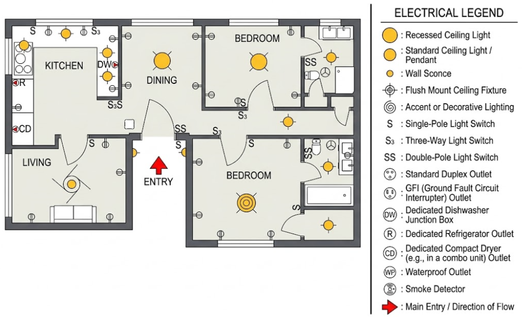
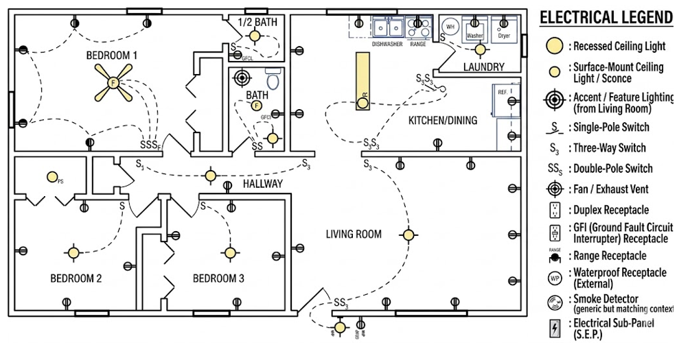
Prepare the legend before placing symbols. Switches should be near entrance points, sockets should be convenient, and distribution boards must be accessible.

One bedroom electrical layout
One-bedroom layout: identify lamp points, sockets, switches, fan point and distribution-board position.
WAEC teacher explanation
  1. Draw the room outline first.
  2. Prepare a neat legend/key.
  3. Place symbols at practical positions and label each item.
Two bedroom electrical layout A
Two-bedroom layout A: interpret bedroom, living room and service-area electrical points.
WAEC teacher explanation
  1. Count each fitting room by room.
  2. Check that every lamp has a control point.
  3. Keep sockets clear of wet or unsafe positions.
Two bedroom electrical layout B
Two-bedroom layout B: compare switch access and socket distribution across rooms.
WAEC teacher explanation
  1. Start with the legend.
  2. Trace lighting points separately from socket outlets.
  3. Write the quantity schedule clearly.
Three bedroom electrical layout
Three-bedroom layout: larger domestic plan for legend preparation and room-by-room interpretation.
WAEC teacher explanation
  1. Separate bedrooms, living area and kitchen.
  2. Place fittings without covering room labels.
  3. Use the same symbol consistently throughout.
Three bedroom full wiring layout
Three-bedroom full wiring: trace lighting and socket circuits in a complete domestic layout.
WAEC teacher explanation
  1. Follow the supply from the distribution board.
  2. Trace final circuits one at a time.
  3. Use labels for lighting, socket and cooker circuits.
Residential full wiring layout
Residential full wiring: complete house reference for consumer unit, lighting, socket and control-point interpretation.
WAEC teacher explanation
  1. Identify the consumer unit first.
  2. Mark lighting and power circuits separately.
  3. Check that the drawing remains readable after labelling.

B.S. Symbols and Practical Location Symbols

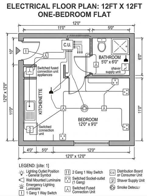
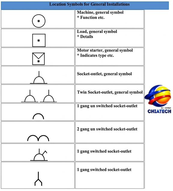
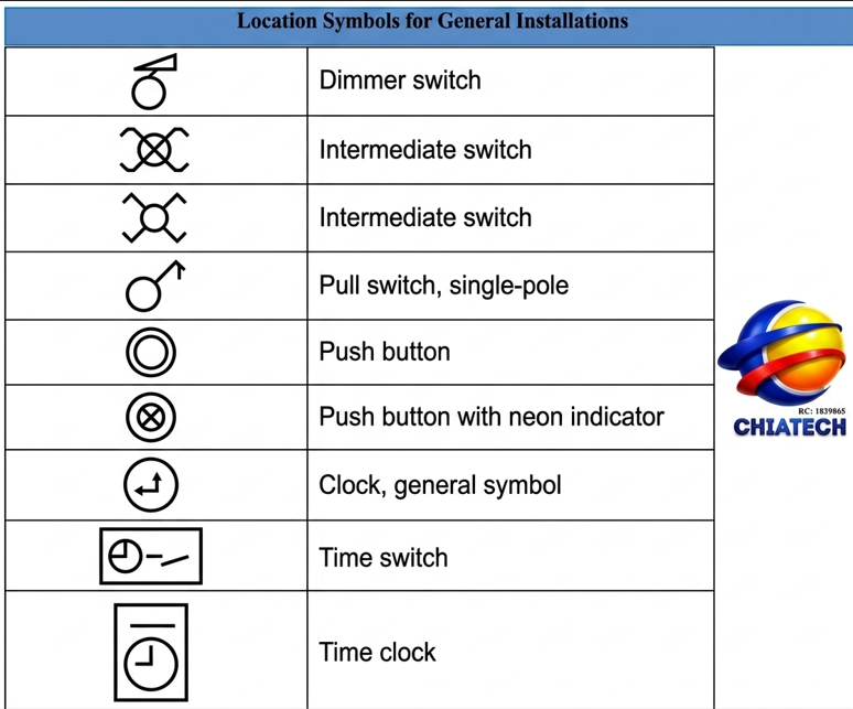
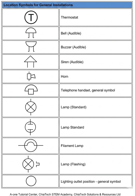
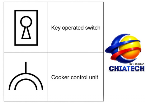
Know the symbol, the name and the use. WAEC often awards marks for correct graphical representation and correct interpretation.

Electrical location symbols general plate one
Location symbols I: common symbols used in domestic installation drawings.
WAEC teacher explanation
  1. Copy the symbol shape carefully.
  2. Write the correct name beside the symbol.
  3. State one practical use when required.
Electrical location symbols general plate three
Location symbols II: additional layout symbols for fittings and outlets.
WAEC teacher explanation
  1. Compare similar symbols before answering.
  2. Do not invent new shapes.
  3. Use the legend to avoid wrong identification.
Electrical location symbols general plate four
Location symbols III: symbols candidates should recognise before layout questions.
WAEC teacher explanation
  1. Draw symbols in pencil first.
  2. Keep the legend aligned.
  3. Use standard names: socket, switch, lamp, fan, cooker control.
Key operated switch and cooker control unit symbols
Cooker/control symbols: key-operated switch and cooker control unit representation.
WAEC teacher explanation
  1. Place cooker control in the kitchen.
  2. Label the control unit clearly.
  3. State that it controls/isolate cooking appliance supply.
Three gang switch symbols
Gang switch symbols: multi-gang switching recognition for practical boards.
WAEC teacher explanation
  1. Count the gangs before naming the switch.
  2. Show each control point neatly.
  3. Avoid mixing one-way and two-way labels.
Three gang switch 3D visual
Gang switch visual: physical appearance of grouped switching accessories.
WAEC teacher explanation
  1. Use the visual to recognise the accessory.
  2. Name the item and state what it controls.
  3. Mention neat mounting and correct polarity where relevant.

Switching, Socket Circuits and Final Sub-Circuits

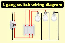
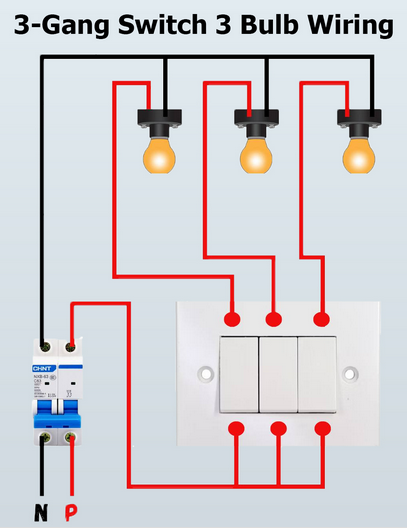
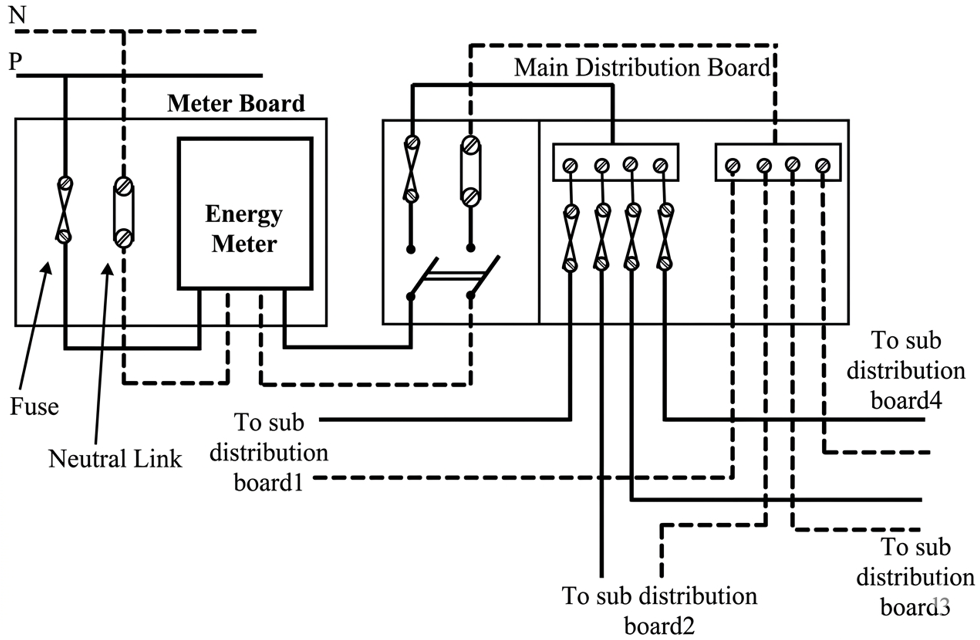
Trace live, neutral and earth paths. The switch must be in the live conductor, and socket circuits must return correctly to the protective device.

Light switching wiring diagram
One-way light switching: basic lamp control wiring for board work.
WAEC teacher explanation
  1. Take live supply to the switch.
  2. Take switched live to the lamp.
  3. Return neutral directly to the lamp.
Two way switching diagram
Two-way switching: one lamp controlled from two positions using two 2-way switches.
WAEC teacher explanation
  1. Mark COM, L1 and L2.
  2. Connect the two strappers L1-L1 and L2-L2.
  3. Feed the lamp from the second common terminal.
Three way switching diagram
Three-position control: intermediate switching logic for corridor or staircase control.
WAEC teacher explanation
  1. Draw the two 2-way end switches.
  2. Place the intermediate switch between the strappers.
  3. Keep strappers straight and labelled.
One lamp controlled by three switches
One lamp, three switches: lamp control from three positions.
WAEC teacher explanation
  1. Use two 2-way switches at the ends.
  2. Use intermediate switch in the middle.
  3. Explain it is suitable for long corridors or staircases.
Two lamps in parallel controlled by switch
Two lamps in parallel: each lamp receives full supply voltage while one switch controls the group.
WAEC teacher explanation
  1. Connect both lamp lives to the switched live.
  2. Connect both neutrals to neutral.
  3. State that one lamp failure should not put out the other.
Ring circuit socket diagram
Ring circuit: both ends of the cable return to the consumer unit.
WAEC teacher explanation
  1. Draw the complete loop first.
  2. Place socket outlets around the loop.
  3. Show spurs only after the ring is complete.
Ring circuit sockets further explained
Ring circuit detail: reinforces ring return path and socket arrangement.
WAEC teacher explanation
  1. State 2.5 mm² cable where required.
  2. State 30 A protective device in past questions.
  3. Keep socket symbols equally spaced.
Radial socket circuit
Radial socket circuit: one path from the distribution board to the outlets.
WAEC teacher explanation
  1. Start at the consumer unit.
  2. Do not return the cable as a ring.
  3. Compare with ring final circuit in the answer.
Spur circuit explanation
Spur explanation: how spurs are taken from ring circuits and why fused spurs are used.
WAEC teacher explanation
  1. Identify the point where the spur leaves the ring.
  2. Show the spur as a branch, not a second ring.
  3. Use fused spur where the branch needs local protection.
Fused spur diagram
Fused spur: local fused connection for a branch circuit or fixed appliance.
WAEC teacher explanation
  1. Name the fused connection unit.
  2. State that the fuse protects the spur/load.
  3. Place it before the fixed appliance.
Ceiling fan wiring diagram
Ceiling fan wiring: fan, regulator, switch and supply connections.
WAEC teacher explanation
  1. Place the fan centrally in the room.
  2. Put regulator near the switch position.
  3. Label live, neutral and regulator connections.

Cables, Conduit, Accessories and Practical Materials

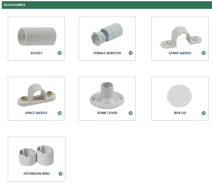
Identify fittings by shape and state the use. Installation answers should mention mechanical protection, earthing, neat routing and correct fixing.

Conduit accessories
Conduit accessories: boxes, bends, inspection fittings and their uses.
WAEC teacher explanation
  1. Name each fitting.
  2. State where it is used in conduit work.
  3. Mention that burrs must be removed before drawing cables.
Circular junction boxes
Circular junction boxes: through, angle, tee and intersection box functions.
WAEC teacher explanation
  1. Count the conduit entries.
  2. Match the entry direction to the box name.
  3. State whether it branches, turns or continues the run.
Electrical accessories
More accessories: switches, holders, sockets and related installation accessories.
WAEC teacher explanation
  1. Identify each accessory by function.
  2. State one use for each.
  3. Avoid confusing accessories with tools.
Wires and cables
Wires and cables: recognise cable forms used in installation work.
WAEC teacher explanation
  1. State conductor and insulation clearly.
  2. Mention current rating or insulation where asked.
  3. Use correct units for cable size in mm².
Armoured cable construction
Armoured cable construction: layers of PVC armoured cable.
WAEC teacher explanation
  1. Label conductor, insulation, armouring and sheath.
  2. State that armour gives mechanical protection.
  3. Mention earthing continuity where applicable.
Typical armoured cable
Typical armoured cable: recognition plate for cable construction questions.
WAEC teacher explanation
  1. Name each visible layer.
  2. State installation precautions.
  3. Protect PVC insulation from excessive heat.
Unarmoured and armoured cable comparison
Unarmoured vs armoured cable: compare mechanical protection and application.
WAEC teacher explanation
  1. Write one difference at a time.
  2. Armoured cable is used where more protection is needed.
  3. Unarmoured cable needs separate protection where exposed.
PV conduit system
PV conduit system: cable routing and protection for Solar PV installation.
WAEC teacher explanation
  1. Keep PV cables protected from weather and abrasion.
  2. Use neat conduit routes and saddles.
  3. Label d.c. side conductors and protection points.

Earthing, Protection, Testing and Safety Plates

Protective devices reduce shock, leakage, overcurrent, fire and equipment damage. Testing answers must state instrument, connection method and acceptable reading.

Earthing system
Earthing system: low-resistance path for fault current.
WAEC teacher explanation
  1. Identify electrode, earth lead and exposed metalwork.
  2. State that earthing improves safety.
  3. Mention low resistance path for fault current.
Earth plate
Earth plate: plate electrode arrangement for earthing.
WAEC teacher explanation
  1. Label earth plate and conductor.
  2. State it is buried in the ground.
  3. Mention moisture/soil contact improves effectiveness.
Earth rod inside pit
Earth rod in pit: rod electrode and inspection pit recognition.
WAEC teacher explanation
  1. Name the earth rod.
  2. Show connection to earth conductor.
  3. State that the pit allows inspection and testing.
Earth leakage circuit breaker
ELCB/RCD protection: earth leakage and shock protection device recognition.
WAEC teacher explanation
  1. State that it trips on leakage current.
  2. Mention electric-shock protection.
  3. Do not confuse with ordinary switch.
Fuse types
Fuses: overcurrent protection by melting fuse element.
WAEC teacher explanation
  1. State fuse is in the live conductor.
  2. Explain it melts under excess current.
  3. Use correct rating to prevent damage or fire.
Motor protection
Motor protection: protects motors from overload, fault and unsafe operation.
WAEC teacher explanation
  1. Name the protective part shown.
  2. State the fault it protects against.
  3. Link overload/single phasing to overheating.
Electrical danger plate
Danger plate: warning sign for electrical hazards.
WAEC teacher explanation
  1. Identify the warning sign.
  2. State the safety instruction.
  3. Mention isolation before work.
Electrical emergency safety plate
Emergency safety: practical response to electrical emergency.
WAEC teacher explanation
  1. Switch off supply first.
  2. Use dry insulating material if immediate isolation is not possible.
  3. Call for medical help and give first aid.

Generation, Transmission and Overhead-Line Hardware

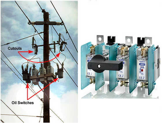
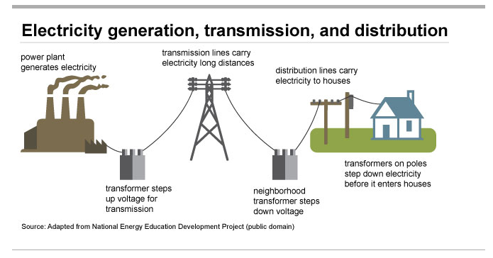
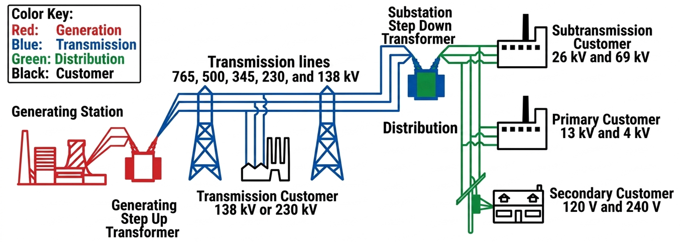
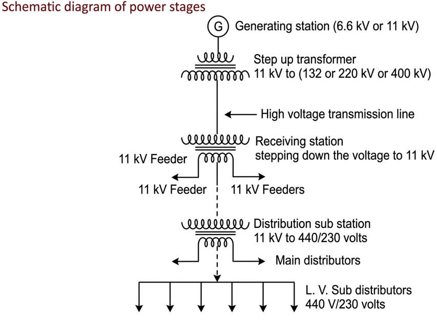
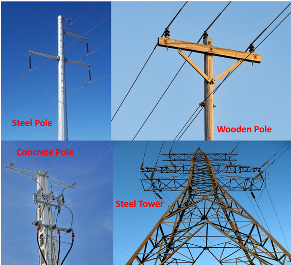
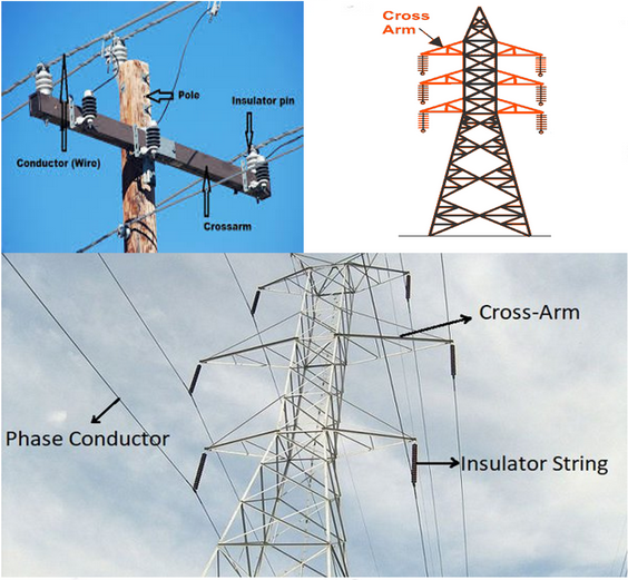
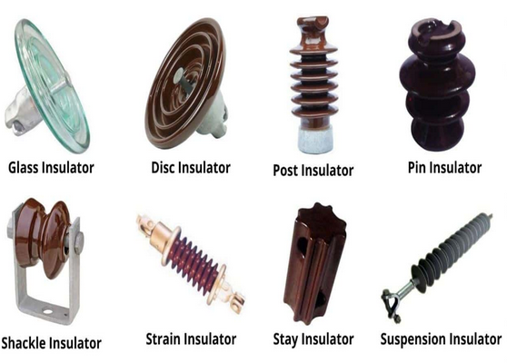
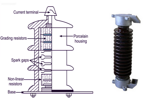
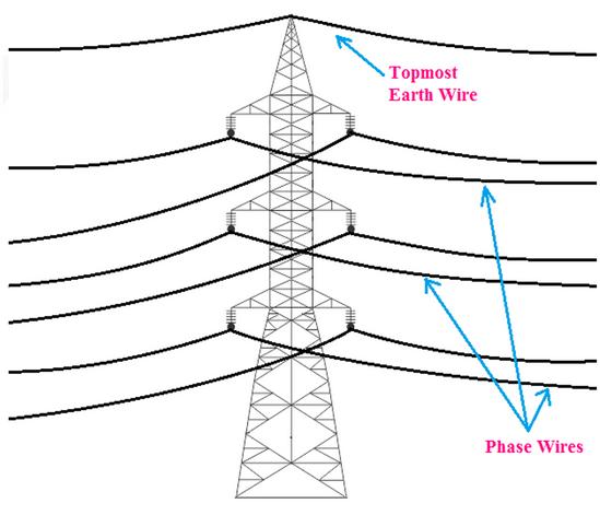
These plates strengthen supply-sequence questions and practical recognition of outdoor distribution components.

Electricity generation and distribution
Generation and distribution: sequence from generation to consumer supply.
WAEC teacher explanation
  1. Start from generating station.
  2. Move through transmission, distribution and consumer installation.
  3. Use arrows to show energy flow.
Generation to distribution
Generation to distribution: power stages before consumer final circuits.
WAEC teacher explanation
  1. Name each stage in order.
  2. Mention transformer action where voltage changes.
  3. End at consumer distribution board/final circuit.
Schematic diagram of power stages
Power stages schematic: clear block diagram of supply stages.
WAEC teacher explanation
  1. Use blocks for each stage.
  2. Keep arrows in one direction.
  3. Label high-voltage and low-voltage sides where shown.
Line supports
Line supports: overhead support recognition.
WAEC teacher explanation
  1. Name the support.
  2. State it carries conductors safely.
  3. Mention clearance and mechanical strength.
Crossarms
Crossarms: supports overhead conductors and insulators.
WAEC teacher explanation
  1. Identify crossarm position.
  2. State that it holds insulators/conductors apart.
  3. Mention spacing reduces contact and faults.
Insulators
Insulators: support conductors while preventing leakage to support structures.
WAEC teacher explanation
  1. Name the insulator.
  2. State that it has high resistance.
  3. Mention use on overhead lines.
Lightning arrestor
Lightning arrestor: protects installation from lightning surges.
WAEC teacher explanation
  1. Name the device.
  2. State it diverts surge to earth.
  3. Connect the answer to earthing.
Transmission line earth wire
Transmission earth wire: overhead protection wire connected to earth.
WAEC teacher explanation
  1. Identify the earth wire above phase conductors.
  2. State it shields the line from lightning.
  3. Mention connection to earth.

Machines, Generators, Motors, Batteries and Winding

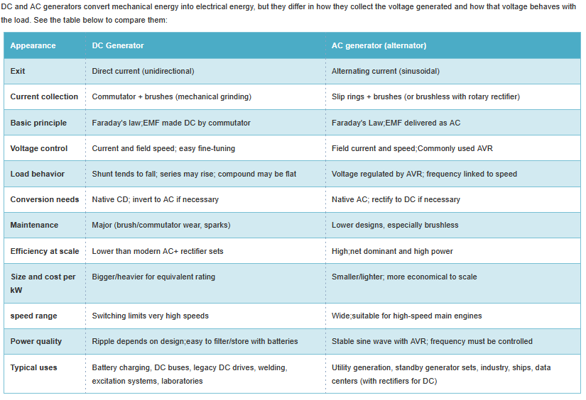
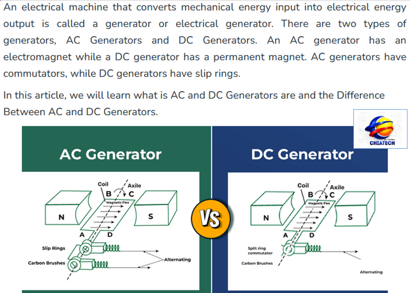
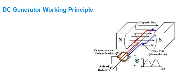
Use these plates for machine identification, generator action, induction motor operation, star/delta connections and armature winding comparison.

Concept of direct current
Concept of d.c.: direct current flows in one direction.
WAEC teacher explanation
  1. State polarity remains fixed.
  2. Use battery/PV examples where required.
  3. Draw one-direction arrows clearly.
Concept of alternating current
Concept of a.c.: alternating current changes direction periodically.
WAEC teacher explanation
  1. State polarity reverses repeatedly.
  2. Mention 50 Hz supply where relevant.
  3. Use sine-wave idea for a.c. output.
DC and AC generators
D.C. and A.C. generators: compare commutator and slip-ring output.
WAEC teacher explanation
  1. D.C. generator uses split-ring commutator.
  2. A.C. generator uses slip rings.
  3. Both depend on electromagnetic induction.
AC generator versus DC generator
A.C. generator vs D.C. generator: identify output and collecting arrangement.
WAEC teacher explanation
  1. Label brushes and rings/commutator.
  2. State output type.
  3. Explain one difference in a full sentence.
DC generator working
D.C. generator working: mechanical rotation produces electrical output.
WAEC teacher explanation
  1. Show motion of coil in magnetic field.
  2. Label N and S poles.
  3. State induced e.m.f. is collected by brushes.
DC motor
D.C. motor: electrical energy converted to mechanical rotation.
WAEC teacher explanation
  1. Name brushes, commutator, armature and field.
  2. Mention back e.m.f. in running motor.
  3. State common uses where asked.
AC motor
A.C. motor: alternating-current motor for practical loads.
WAEC teacher explanation
  1. Identify stator and rotor.
  2. State a.c. supply produces rotating magnetic field.
  3. Mention common applications such as fan, grinder or pump.
AC versus DC motors
A.C. vs D.C. motors: compare supply, construction and speed-control ideas.
WAEC teacher explanation
  1. Write differences in paired lines.
  2. Mention d.c. commutator/brushes.
  3. Mention many induction motors are rugged and brushless.
Three phase motor connection
Three-phase motor terminals: identify start and finish terminals before connection.
WAEC teacher explanation
  1. Name A1, B1, C1 as starts.
  2. Name A2, B2, C2 as finishes.
  3. Connect star or delta only after naming terminals.
Star and delta connection
Star vs delta: star reduces starting current; delta is normal full-power running connection.
WAEC teacher explanation
  1. For star, join the three ends together.
  2. For delta, connect each end to the next start.
  3. Use correct line terminals.
Single phasing of motor
Single phasing: one supply line opens and the motor overheats.
WAEC teacher explanation
  1. State one phase is lost.
  2. Mention motor may continue running but overheats.
  3. Protect with overload/single-phase protection.
Lap and wave armature winding
Lap and wave winding: armature winding comparison for d.c. machines.
WAEC teacher explanation
  1. Lap: adjacent commutator segments and many parallel paths.
  2. Wave: segments some distance apart and two parallel paths.
  3. Use lap for high current and wave for high voltage.
Leclanche cell
Leclanche cell: label carbon, zinc, electrolyte, container and polarity.
WAEC teacher explanation
  1. Name each labelled part.
  2. State e.m.f. is about 1.5 V.
  3. Mention local action and polarization as defects.

Basic Electrical Symbols Library

These symbols are very important in Electrical Installation work and should be familiar to all candidates.

Your browser could not display the PDF inline. Open the Basic Electrical Symbols Guide.

Objective Drill Lab

WAEC-style objective practice from past questions and expert tutor guidance. Open each set, answer first, then view the teaching explanation.

Past-Question Tutorial Class

Attempt each question first, then open the answer guide. Diagrams are displayed where the question or answer needs visual evidence.

Post-Test Upgrade: Machines, Generators and Windings

Study this section after Tests 1-10. It strengthens the machine, generator, induction motor and armature-winding questions that often separate average answers from excellent practical answers.

Generator Principle

  • Mechanical rotation changes magnetic flux linkage and induces e.m.f. in the coil.
  • D.C. generator output is made unidirectional by the split-ring commutator.
  • A.C. generator output is alternating because slip rings do not reverse the coil connection every half-turn.

Induction Motor Principle

  • The stator creates a rotating magnetic field from a.c. supply.
  • Rotor current is induced by the changing field, so the rotor does not need direct electrical connection.
  • The rotor follows the rotating field and delivers mechanical output through the shaft.

Exam Drawing Standard

  • Use a ruler for terminal boards, coil links, conductors and supply paths.
  • Label before explaining: N/S poles, brushes, commutator/slip rings, stator, rotor and shaft.
  • Give one function for each labelled part when the question asks for function.

Lap/Wave Quick Table

  • Lap winding: adjacent commutator connection, A = P for simplex, low voltage/high current.
  • Wave winding: distant commutator connection, A = 2 for simplex, high voltage/low current.
  • Do not confuse winding type with a.c./d.c. supply; it is an armature winding arrangement.
DC and AC generator comparison
Generator comparison: connects generator structure to output type and collection method.
WAEC teacher explanation
  1. Identify the rotating coil and magnetic field.
  2. Name commutator for d.c. and slip rings for a.c.
  3. State the energy conversion: mechanical to electrical.
AC induction motor
A.C. induction motor: links stator field, rotor current and shaft output.
WAEC teacher explanation
  1. Label stator and rotor.
  2. State the rotating magnetic field idea.
  3. Explain that induced rotor current produces torque.
Lap and wave winding comparison
Lap and wave winding: machine-winding comparison for higher-grade d.c. machine answers.
WAEC teacher explanation
  1. Write A = P for simplex lap and A = 2 for simplex wave.
  2. State machine use: lap for high current; wave for high voltage.
  3. Keep coil paths neat and label the commutator.

Technical Reference Base

These notes are aligned with examinable generator action, induction-motor operation and armature-winding comparison. The explanations are written for WAEC Electrical Installation and Maintenance Work answers.

Class Interaction

Ask questions, reply to classmates, react to helpful explanations and upload one small support file when needed. Upload limit: 1 MB.